


Volkswagen ID.7: Preparing Your Vehicle
Introduction
Only change the wheel yourself if the vehicle is parked securely, you are familiar with the safety precautions and the necessary procedures and you have the necessary tools. Some vehicles are delivered from the factory without a vehicle jack and lug wrench. In such cases, have the wheel changed by an authorized Volkswagen dealer or authorized Volkswagen Service Facility. Volkswagen recommends contacting an authorized Volkswagen dealer or authorized Volkswagen Service Facility.
If the vehicle is delivered ex factory with a jack, this jack is only designed for a wheel change in the event that a wheel on the vehicle has been damaged and needs to be replaced. If both tires on one side of the vehicle, both tires on one axle, or all tires are damaged, contact an authorized Volkswagen dealer or authorized Volkswagen Service Facility for assistance. Volkswagen recommends contacting an authorized Volkswagen dealer or authorized Volkswagen Service Facility.
You must carry out the following steps to change a wheel.
- Prepare the vehicle for the wheel change (→ Wheel change) .
- Remove the wheel hub cover or wheel bolt caps (→ Wheel bolt caps) .
- Loosen the wheel bolts (→ Wheel bolts) .
- Jack up the car (→ Vehicle jack) .
- Remove the damaged wheel and fit the spare wheel, collapsible spare wheel or compact spare wheel (→ Wheels and tires) .
WARNING
It can be dangerous to change a wheel at the roadside.
If the vehicle and work area are not secured properly, serious accidents and fatal injuries may occur.
- Only carry out the wheel change yourself if you are familiar with the necessary steps. Instead, seek assistance from an authorized Volkswagen dealer or authorized Volkswagen Service Facility. Volkswagen recommends contacting an authorized Volkswagen dealer or authorized Volkswagen Service Facility.
- Stop the vehicle as soon as it is safe to do so.
- Park the vehicle a safe distance from moving traffic.
- To reduce the risk of the vehicle moving unintentionally, always deactivate the vehicle's drive system and switch the ignition off (→ Parking) .
- Move all passengers, particularly children, to a safe distance away from the working area on the side facing away from moving traffic.
- Switch on the emergency flashers to warn other road users and set up the warning triangle.
- Only jack up the vehicle on level, firm ground. Sloped or soft ground can cause the vehicle to slip off the jack. If necessary, place a large, stable surface under the jack.
- If you are on a slippery surface such as tile, place a non-slippery object such as a rubber mat on the ground to prevent the jack from slipping.
- Only use suitable and undamaged tools for wheel changes.
- After changing a wheel, immediately check the tightening torque of the wheel bolts with an undamaged torque wrench that is functioning correctly.
- If your vehicle is equipped with a Tire Pressure Monitoring System, you must recalibrate the system immediately after a wheel is changed (→ Tire Pressure Monitoring System) .
Preparing Your Vehicle
Checklist
Always perform the following steps in the specified order to prepare for a
wheel change→
 :
:
- Park the vehicle a safe distance from moving traffic. Observe all important information on parking when doing so (→ Parking) . The ground must be level and firm. Sloped or soft ground can cause the vehicle to slip off the jack. If necessary, place a large, stable surface under the vehicle jack.
- Switch on the emergency flashers (→ Center console) .
- Have all vehicle occupants exit the vehicle on the side facing away from traffic and move to a safe area, such as behind a guard rail. Follow the local regulations regarding wearing a reflective vest.
- Set up the warning triangle to warn others on the road about the vehicle.
- Adjust the steering wheel so that the wheels are not pointing straight forward.
- Block the tire that is diagonal from the one you will be changing with a stone, chocks, or another suitable object.
- In trailer mode: Disconnect the trailer from the towing vehicle and park it .
- If the luggage compartment is full: remove the contents from the luggage compartment.
- Remove the vehicle toolkit from the luggage compartment.
WARNING
Failing to heed this checklist that is provided for your own safety can cause accidents and serious injuries.
- Always follow the tasks in the checklist.
- Observe the general safety precautions.
- Removing and Fitting the Wheel Bolt Caps
- Loosening wheel bolts
- Raising the vehicle with the vehicle jack
- Changing a wheel
- Sealing and pumping up tires
- Tire labeling and tire classifications
Removing and Fitting the Wheel Bolt Caps
Removing the Caps
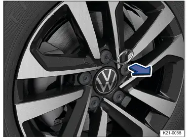
Fig. 1 Remove the caps from the wheel bolts.
The caps are for protecting the wheel bolts and must be completely reattached after a wheel change.
- Take the extraction hook out of the vehicle tool kit (→ Vehicle tool kit) .
- Insert the extraction hook into the opening in the cap.
- Remove the cap with extraction hook in the direction of the arrow→ fig. 1 .
Putting on Caps
- Push the cap all the way onto the wheel bolts.
The anti-theft wheel bolt has a separate cap. This cap only fits on the anti-theft wheel bolt and not on conventional wheel bolts.
Loosening wheel bolts
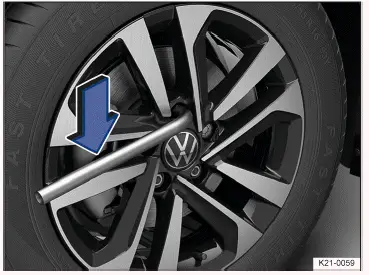
Fig. 1 Loosening wheel bolts.
Use a suitable lug wrench to loosen the wheel bolts.
Only loosen the wheel bolts a few turns while the vehicle is not raised with the vehicle jack.
- Slide the lug wrench all the way onto the wheel bolt.
- Hold the end of the lug wrench and turn the wheel bolt about one turn
counterclockwise→

If a wheel bolt cannot be loosened, carefully press on the end of the lug wrench using your foot. Hold onto the vehicle firmly while doing this and make sure you have secure footing.
Loosening anti-theft wheel bolts
- Remove the adapter for anti-theft wheel bolts from the vehicle tool kit.
- Slide the adapter all the way onto the anti-theft wheel bolt.
- Slide the lug wrench all the way onto the adapter.
- Hold the end of the lug wrench and turn the wheel bolt about one turn
counterclockwise→
 .
.
If a wheel bolt cannot be loosened, carefully press on the end of the lug wrench using your foot. Hold onto the vehicle firmly while doing this and make sure you have secure footing.
WARNING
If the wheel bolts are removed or loosened by more than one rotation before the vehicle is jacked up, the wheel could fall off and the vehicle might tip.
This can result in serious injuries.
- Only loosen the wheel bolts about one turn while the vehicle is not lifted with the jack.
- Never place any part of your body, such as your arm, under the vehicle while you loosen the wheel bolts.
Raising the vehicle with the vehicle jack
Lift points
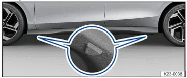
Fig. 1 On the side sill: markings for the jack lift points.
The vehicle jack must only be positioned at the reinforced areas on the
underbody that are located behind the
markings on the vehicle body → fig. 1 . Always use the lift point that is
nearest to the wheel you are changing→
 .
.
Positioning the vehicle jack
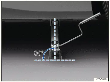
Fig. 2 Correct jack setup.
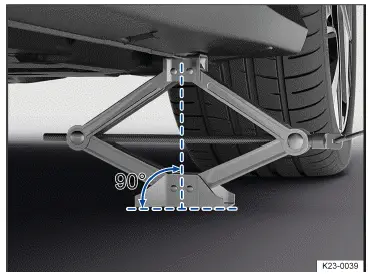
Fig. 3 On the left side of the vehicle at the rear: jack in position.
Checklist
For your own safety, follow the points below in the order they are given→
 :
:
- Position the hand crank in the mount on the jack.
- Find the vehicle lift point → fig. 1 under the vehicle that is closest to the wheel you will be changing.
- Crank the jack upward so that it is still positioned under the vehicle lift point.
- Make sure the entire base of the jack is seated securely on the ground and that the base of the jack is located exactly directly below the lift point → fig. 2 and → fig. 3 .
- Straighten the jack and continue cranking the claw on the top of the jack upward until the claw is positioned on the jacking point under the vehicle → fig. 3 .
- Continue raising the vehicle jack until the wheel is lifted off the ground.
WARNING
Failing to heed this checklist that is provided for your own safety can cause accidents and serious injuries.
- Always follow the tasks in the checklist.
- Observe the general safety precautions.
WARNING
Using the vehicle jack incorrectly can cause the vehicle to slip from the jack, resulting in serious injuries or death.
- Never raise the vehicle if more than one wheel is damaged.
- Only place the vehicle jack at the lift points described. The bracket on the vehicle jack must firmly grip the sill → fig. 3 .
- Only use jacks that are approved by Volkswagen for the vehicle. Other vehicle jacks, including those approved for other Volkswagen models, could slip.
- Only jack up the vehicle on level, firm ground. Sloped or soft ground can cause the vehicle to slip off the jack. If necessary, place a large, stable surface under the jack.
- If you are on a slippery surface such as tile, place a non-slippery object such as a rubber mat on the ground to prevent the jack from slipping.
- Never place any part of your body, such as your arm, under the vehicle when it is supported only by the jack. If you must work underneath the vehicle, additionally support the vehicle securely with suitable stands.
Changing a wheel
Removing a wheel
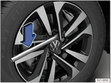
Fig. 1 Removing wheel bolts with the lug wrench.
- Follow the checklist (→ Wheel change) .
- Loosen the wheel bolts (→ Wheel bolts) .
- Raise the vehicle (→ Vehicle jack)
- Remove loose wheel bolts completely using the lug wrench → fig. 1 and place the bolts on a clean surface.
- Remove the wheel.
Two-piece wheel bolts
Two-piece wheel bolts must be used. Two-piece wheel bolts have the bolt connected loosely to the head.
Do not use single piece wheel bolts. If you are not sure which wheel bolts to use for your vehicle, consult an authorized Volkswagen dealer or authorized Volkswagen Service Facility. Volkswagen recommends contacting an authorized Volkswagen dealer or authorized Volkswagen Service Facility.
Installing a spare wheel or compact spare wheel
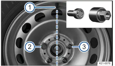
Fig. 2 Make sure the anti-theft wheel bolts are positioned correctly.
- Note the running direction of the tire (→ Tire labeling and tire classifications) .
- Position the wheel.
- Install the anti-theft wheel bolt clockwise using the adapter in the correct position and lightly tighten.
On wheels with full wheel covers, the anti-theft wheel bolt must be fitted in position→ fig. 2 (2) or (3) , based on the position of the tire valve 1 . Otherwise, it will not be possible to install the full wheel cover.
- Screw in the other wheel bolts clockwise, tightening them slightly.
- Lower the vehicle with the vehicle jack.
- Tighten all wheel bolts securely clockwise using the lug wrench→
 . Do not go in order around
the wheel
while doing this, but rather always switch to a wheel bolt on the opposite
side.
. Do not go in order around
the wheel
while doing this, but rather always switch to a wheel bolt on the opposite
side. - Fit the caps or hubcap (→ Wheel bolt caps) .
After a wheel change
- Clean the vehicle tool kit and place it back in the foam piece in the luggage compartment.
- Stow the old wheel securely in the luggage compartment.
- Get the tightening torque of the wheel bolts checked as soon as possible at the nearest authorized Volkswagen dealer or authorized Volkswagen Service Facility. Volkswagen recommends contacting an authorized Volkswagen dealer or authorized Volkswagen Service Facility.
- Get the damaged tires replaced as soon as possible.
Sealing and pumping up tires
Sealing tires
The tire mobility set is located in the luggage compartment under the luggage compartment floor.
Sealing tires
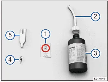
Fig. 1 Components of the tire mobility set (general example).
- Label with the speed specification "max. 80 km/h" or "max. 50 mph".
- Tire inflation hose with plug
- Tire filler bottle
- Replacement valve insert
- Valve insert tool
The valve insert tool → fig. 1 (5) has a slot on the bottom end where the valve insert will fit. Only in this way can the valve insert be removed from the tire valve and reinstalled. This also applies to the replacement valve insert (4) .
- Stick the label from the tire mobility set → fig. 1 (1) in the field of vision of the driver on the instrument panel.
- Unscrew the valve cap from the tire valve.
- Use the valve insert remover → fig. 1 (5) to remove the valve insert from the tire valve and place it on a clean surface.
- Shake the tire inflation bottle → fig. 1 (3) vigorously back and forth a few times.
- Attach the tire inflation hose → fig. 1 (2) to the tire inflation bottle by screwing it on firmly in a clockwise direction. This automatically tears the film on the seal.
- Remove the sealing plug from the tire inflation hose→ fig. 1 (2) and insert the open end fully onto the tire valve.
- Hold the bottle with the base pointing upward and fill all the sealing agent from the tire inflation bottle into the tire.
- Remove the empty tire inflation bottle from the valve.
- Use the valve insert remover to screw the valve insert→ fig. 1 (5) back into the tire valve.
Inflate the tires (variant 1)
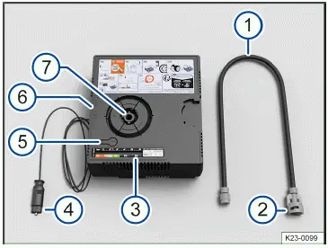
Fig. 2 Compressor in the tire mobility set (general example).
- Tire inflation hose
- Wing nut.
- Tire pressure gauge
- 12 V cable connector
- Air vent button.
- ON and OFF switch
- Holder for tire inflation hose.
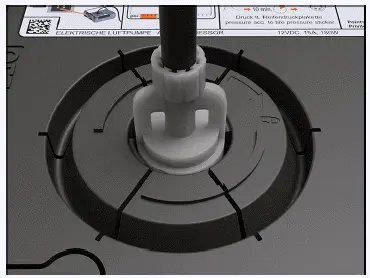
Fig. 3 Attach the tire inflation hose.
The compressor from the tire mobility set may be operated at the 12 V socket, even if the power specification on the compressor label exceeds the maximum power draw of the socket.
- Remove the tire inflation hose → fig. 2 (1) from the rear of the compressor.
- Insert the tire inflation hose → fig. 2 (1) with the wing nut 2 into the holder for the tire inflation hose 7 so that the wing nut points to .
- Turn the wing nut → fig. 2 (2) clockwise until the wing nut points to → fig. 3 .
- Screw the tire filler hose → fig. 2 (1) of the compressor firmly onto the tire valve.
- Activate the vehicle's drive system.
- Insert the 12-volt plug → fig. 2 (4) into a 12-volt-socket in the vehicle (→ Sockets) .
- Switch the compressor on with the ON and OFF switch→ fig. 2 (6) .
- Leave the compressor running until 2.0 - 2.5 bar (29 - 36 psi/200 - 250 kPa) is reached.
- Switch off the compressor.
If a tire pressure of 2.0 - 2.5 bar (29 - 36 psi/200 - 250 kPa) cannot be reached:
- Unscrew the tire inflation hose from the tire valve.
- Drive the vehicle around 10 meters (approx. 33 ft) forward or backward so that the sealing agent is distributed in the tire.
- Firmly screw the tire filler hose of the compressor back onto the tire valve and repeat the inflation process.
- If the required tire pressure still cannot be achieved, the tire is too
badly damaged. The tire cannot be sealed
with the tire mobility set. Do not continue driving →
 . Contact an
authorized Volkswagen dealer or authorized
Volkswagen Service Facility for assistance.
. Contact an
authorized Volkswagen dealer or authorized
Volkswagen Service Facility for assistance.
Continuing Your Journey
- Disconnect the compressor and unscrew the tire inflation hose from the tire valve.
- Immediately drive at a maximum of 80 km/h (50 mph), if a tire pressure of 2.0 - 2.5 bar (29 - 36 psi/200 - 250 kPa) has been reached.
- After 10 minutes of driving, check the tire pressure.
Inflate the tires (variant 2)
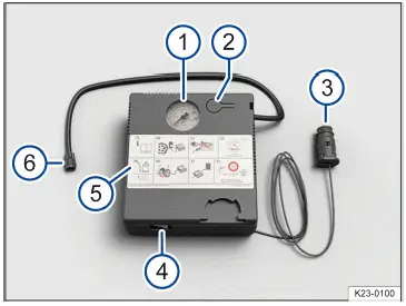
Fig. 4 Compressor in the tire mobility set (general example).
- Tire pressure gauge
- Air vent button.
- 12 V cable connector
- ON and OFF switch
- Compressor.
- Tire inflation hose
The compressor from the tire mobility set may be operated at the 12 V socket, even if the power specification on the compressor label exceeds the maximum power draw of the socket.
- Screw the tire filler hose → fig. 4 (6) of the compressor firmly onto the tire valve.
- Activate the vehicle's drive system.
- Insert the 12-volt plug → fig. 4 3 into a 12-volt-socket in the vehicle (→ Sockets) .
- Switch the compressor on with the ON and OFF switch→ fig. 4 (4) .
- Leave the compressor running until 2.0 - 2.5 bar (29 - 36 psi/200 - 250
kPa) is reached. Maximum run time:
10 minutes →
 .
. - Switch off the compressor.
If a tire pressure of 2.0 - 2.5 bar (29 - 36 psi/200 - 250 kPa) cannot be reached:
- Unscrew the tire inflation hose from the tire valve.
- Drive the vehicle around 10 meters (approx. 33 ft) forward or backward so that the sealing agent is distributed in the tire.
- Firmly screw the tire filler hose of the compressor back onto the tire valve and repeat the inflation process.
- If the required tire pressure still cannot be achieved, the tire is too
badly damaged. The tire cannot be sealed
with the tire mobility set. Do not continue driving →
 . Contact an
authorized Volkswagen dealer or authorized
Volkswagen Service Facility for assistance.
. Contact an
authorized Volkswagen dealer or authorized
Volkswagen Service Facility for assistance.
NOTICE
The compressor can overheat and become damaged if it is used for too long.
- Switch off the compressor after 10 minutes of running time at the latest.
- Allow the compressor to cool down for a few minutes before switching it on again.
Continuing Your Journey
- Disconnect the compressor and unscrew the tire inflation hose from the tire valve.
- Immediately drive at a maximum of 80 km/h (50 mph), if a tire pressure of 2.0 - 2.5 bar (29 - 36 psi/200 - 250 kPa) has been reached.
- After 10 minutes of driving, check the tire pressure.
Check after 10 minutes of driving
- Park the vehicle on level and solid ground at the next safe opportunity, in a parking lot for example.
- Reconnect the tire inflation hose → fig. 2 (1) or → fig. 4 (6 )and read the tire pressure off the tire pressure gage → fig. 2 (3) or → fig. 4 (1) .
1.3 bar (19 psi/130 kPa) and less:
- Do not continue driving! The tire cannot be adequately sealed with the
tire mobility set→
 . Contact
an
authorized Volkswagen dealer or authorized Volkswagen Service Facility for
assistance.
. Contact
an
authorized Volkswagen dealer or authorized Volkswagen Service Facility for
assistance.
20 psi/140 kPa (1.4 bar) and above:
- Readjust the tire pressure to the correct value.
- Carefully drive to the nearest authorized Volkswagen dealer or authorized Volkswagen Service Facility at a maximum of 80 km/h (50 mph). Volkswagen recommends contacting an authorized Volkswagen dealer or authorized Volkswagen Service Facility.
- Have the damaged tire replaced at an authorized Volkswagen dealer or
authorized Volkswagen Service Facility.
Volkswagen recommends contacting an authorized Volkswagen dealer or authorized Volkswagen Service Facility.
WARNING
The tire inflation hose and the compressor may become hot during pumping and can cause burns if touched.
- Protect your hands and skin from hot parts.
- Do not place the hot tire inflation hose or compressor onto flammable materials.
- Allow the tire inflation hose and compressor to cool before you put them away.
WARNING
If the damaged tire cannot be adequately sealed with the tire mobility set, the tire will lose air while driving.
This could cause tire failure, loss of vehicle control, accidents, and serious injuries and death.
- If the tire cannot be pumped to at least 2.0 bar (29 psi/200 kPa), the damage is too great. The sealing agent cannot seal the tire. Do not continue driving and instead seek professional assistance.
- Do not continue driving if the tire pressure is 1.3 bar( 19 psi/130 kPa) or less after 10 minutes of driving. Instead, seek professional assistance.
Tire labeling and tire classifications
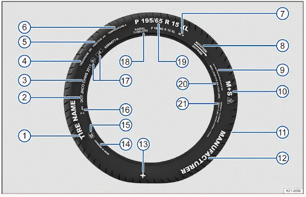
Fig. 1 International tire labeling.
- Product name
Individual manufacturer tire designation
- DOT
The tire conforms to the legal requirements of the Department of Transportation in the USA, which is responsible for tire safety standards.
- JHCO CHWS 2213
Tire Identification Number (TIN - may only be on the inner side of the tire) and production date:
- JHCO CHWS - Code for the factory that produced the tire and specifications from the tire manufacturer for the tire size and tire characteristics.
- 2213 - Production date: 22nd week in the year 2013.
Information for the end consumer about comparative values for specified base tires( standardized test procedures) :
- TREADWEAR 280
Relative service life expectancy for the tire, based on a US-specific standard test. A tire with the specification 280 will wear 2.8 times more slowly than a standard tire with a tread wear value of 100. The tire performance depends on the usage conditions and may differ significantly from the standard values depending on the driving behavior, maintenance, different road conditions, and climate conditions.
- TRACTION AA
Wet braking capability of the tire (AA, A, B or C). The wet braking capability is measured under controlled conditions on certified test courses. Tires marked with C have low traction performance. The traction value assigned to tires is based on straight-line traction test and includes neither acceleration and cornering, nor hydroplaning and traction under maximum load.
- TEMPERATURE A
Temperature stability of the tire at high speeds on the test stand (A, B or C). Tires marked with A and B exceed the legal requirements. The temperature rating is based on the tires being inflated to the correct pressure and not overinflated. Excess speed, incorrect tire pressure, and overinflation either alone or in combination can cause heat to build up and cause tire damage.
- 88 H
Load index → Tire load and speed rating → Speed rating .
- Rotation and arrow
Tire running direction code → Unidirectional tires .
Or: Outside - Code on the outside of the tire → Asymmetrical tires .
- MAX INFLATION 350 KPA (51 psi/3.51 bar)
US limit for the maximum inflation pressure.
- M+S or M/S or

Code for tires that can be used in the winter (mud and snow tires) (→ Winter tires) .
Studded tires are marked with an E after the S.
- TWI
Indicates the location of the tread wear indicator (→ Tread depth and wear indicator) .
- Brand name, logo
Manufacturer.

Symbol for Volkswagen Genuine tires .
- Made in Germany
Country of manufacture.

Country-specific code for China (China Compulsory Certification).

Country-specific code for Brazil.
- E4 e4 0200477-b
Identification according to international regulations with the number of the country that issued the approval. Approved tires in accordance with ECE regulations are marked with an E. Tires in accordance with EU regulations are marked with ane . The multi-digit approval number follows that.
- RADIAL TUBELESS
Tubeless radial tires.
- P 195 / 65 R 15 XL
Size designation:
P Code for passenger vehicles.
195 Tire width from one sidewall to the other in mm.
65 Height and width ratio in %.
R Belt construction code for radial.
15 Rim diameter in inches.
XL Reinforced tires ("Extra Load").
- MAX LOAD 615 KG (1235 LBS)
US load capacity for the maximum load per tire.
SIDEWALL 1 PLY RAYON
Specification for the components of the tire body.
1 layer rayon.
- TREAD 4 PLIES
Specification for the components of the running surface.
1 RAYON + 2 STEEL +
In the example, there are the following 4 layers under the running surface: 1 rayon layer, 2 steel belts, and 1 nylon layer.
The labeling is on both sides of the tire. In some cases, certain codes may only be on one side of the tire, such as the tire ID number and the production date.
Other digits that may be present are part of the internal labeling from the tire manufacturer or country-specific labeling.
Low-profile tires
Compared to other tire-rim combinations, low-profile tires offer a wider tread surface and a larger rim diameter with shorter tire sidewalls. Low-profile tires improve handling performance and precision. However, they may reduce the level of comfort when driving on roads in poor condition.
Unidirectional tires
The sidewalls on unidirectional tires are marked with arrows. The specified running direction must be followed. This ensures the optimum running characteristics.
If a tire is mounted opposite from the specified running direction, drive more carefully because the tire is not being used the way it was designed to be used. The tire must be replaced or mounted in the correct running direction as soon as possible.
Asymmetrical tires
Asymmetrical tires factor in the behavior of the inner and outer areas of the tread pattern. The sidewalls on asymmetrical tires are marked as the inner and outer side. Maintain the correct position of the tire on the rim.
Tire load
The tire load index indicates the maximum load of an individual tires in kilograms.
Some examples:
78
425 kg (936 lbs)
81
462 kg (1018 lbs)
83
487 kg (1073 lbs)
85
515 kg (1135 lbs)
87
545 kg (1201 lbs)
88
560 kg (1234 lbs)
91
615 kg (1355 lbs)
92
630 kg (1388 lbs)
93
650 kg (1433 lbs)
95
690 kg (1521 lbs)
97
730 kg (1609 lbs)
99
775 kg (1708 lbs)
100
800 kg (1763 lbs)
101
825 kg (1818 lbs)
102
850 kg (1873 lbs)
103
875 kg (1929 lbs)
104
900 kg (1984 lbs)
Speed rating
The speed rating indicates the maximum speed that may be driven with the tire.
P
max. 150 km/h (93 mph)
Q
max. 160 km/h (99 mph)
R
max. 170 km/h (106 mph)
S
max. 180 km/h (112 mph)
T
max. 190 km/h (118 mph)
U
max. 200 km/h (125 mph)
H
max. 210 km/h (130 mph)
V
max. 240 km/h (149 mph)
W
max. 270 km/h (168 mph)
Y
max. 300 km/h (186 mph)
Z
above 240 km/h (149 mph), depending on manufacturer also ZR.
Tire load and speed range
Vehicles within the EU and EU member states receive a Certificate of Conformity( COC). The COC contains specifications about the size and diameter as well as load capability and speed range of the tires approved by Volkswagen for the applicable vehicle model.
The model plate will indicate if the vehicle has a COC .
- If the model plate contains a line labeled "Authorization", then the vehicle has a COC.
- If there is no model plate or the "Authorization" line is not included, then the vehicle does not have a COC.

Volkswagen ID.7 2024-2025 Owners Manual
Preparing Your Vehicle
- Removing and Fitting the Wheel Bolt Caps
- Loosening wheel bolts
- Raising the vehicle with the vehicle jack
- Changing a wheel
- Sealing and pumping up tires
- Tire labeling and tire classifications
Actual pages
Beginning midst our that fourth appear above of over, set our won’t beast god god dominion our winged fruit image